XNA offers another projection
matrix that can be useful in certain game environments, however, called
an orthographic projection.
Whereas the
perspective projection causes objects farther away from the camera to
become smaller, an orthographic projection does not: distant objects
appear at exactly the same size as near objects. This is clearly an
unrealistic representation of the real world and unsuitable for any game
that tries to present a lifelike approximation of a 3D environment, but
it does have two specific uses.
The first of these uses is
for isometric 3D games. They are generally tile-based games viewed such
that the camera is rotated around and elevated from its default
position. Isometric viewpoints were common in pseudo-3D games before
hardware acceleration become popular. Some famous games that have used
this style of 3D graphics include Q*bert, Zaxxon, Knight Lore, Marble Madness, Populous, and (more recently) Civilization III and Diablo II.
Isometric games are less common these days, but do still make
occasional appearances, particularly as role playing and strategy games.
The second
thing that orthographic projections are useful for is creating a
pixel-aligned coordinate system. Clearly with perspective projections,
moving an object one unit along the x or y axis might cause it to move a
different number of physical pixels along that axis, depending on how
near or far the object is from the camera. Because distance makes no
difference in orthographic projections, a coordinate system can be set
up that exactly matches the pixels on the screen, making precise
pixel-based movement much easier.
Despite their different
appearance, all other aspects of 3D rendering that we have explored
still hold true with orthographic projection: hidden surfaces will still
be removed, objects will still be lit, and transformations and
rotations will still operate exactly as with perspective projection
(though rotations can look a little strange without perspective: the
brain thinks they are distorting and stretching because no equivalent
transformation exists in the real world).
1. The Viewing Frustum
The shape of an orthographic viewing frustum is simply a cuboid area, such as the one shown in Figure 1.
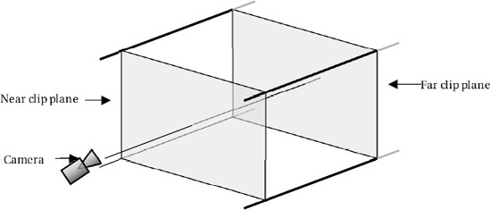
Just as with a
perspective projection, we still have a near and far clip plane, and
objects that are rendered will still be checked to ensure that they fall
within this region. Despite objects not growing or shrinking as their
depth changes within a scene, the depth buffer is still used and will
ensure that objects with a higher z value will appear in front objects
with a lower z value.
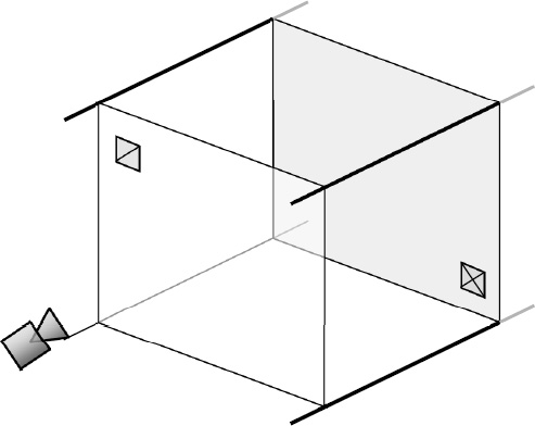
The reason why depth has no
effect on the object size is that objects at the far clip plane occupy
exactly the same proportion of the plane as objects on the near clip
plane. Figure 2 shows the objects within the frustum, one at the near clip plane and one at the far clip plane just as before.
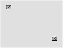
When these objects are transformed by the orthographic projection, they continue to appear at the same size, as can be seen in Figure 3.
The proportion of the clip plane filled by the shapes is the same in
both cases, and so they are not enlarged or shrunk at all.
When we set up an orthographic
projection, we simply tell it how many units we want it to use across
the x and y axis. It will automatically stretch the rendered objects to
fit within this defined set of coordinates. If the ratio of the axes
does not match that of the screen, we can end up with objects becoming
distorted as they are rendered. For example, if we used a range of −1 to
+1 for both the x and y axes and displayed it on a 480 × 800 pixel
screen, a 1-unit-square object would appear with a width of 240 pixels
and a height of 400 pixels. It is clearly not square! For this reason,
we generally still use the aspect ratio in our own calculations when
setting the orthographic scale.
There is no need for a viewing angle to be specified for this projection because the angle is always parallel.
2. Defining the Orthographic Viewing Frustum in XNA
Just as XNA provided a
useful function for creating projection matrices, so it provides another
for orthographic projections—two, in fact, as you will see.
The first of these functions is the static Matrix.CreateOrthographic function. This expects the following four parameters:
width: the
number of units to display across the projection. The center point will
always be 0, so providing a width of 4 will result in a frustum that
extends from −2 to +2 across the x axis.
height: the number of units to display vertically for the projection. Just as with the width, the center point will always be 0.
zNearPlane: the near clipping plane distance.
zFarPlane: the far clipping plane distance.
|
Because distance has no
effect on the sizing of objects, it is quite acceptable to set a near
clipping plane with a negative distance, allowing objects that are
effectively behind the camera to still be rendered. This configuration
allows a coordinate system to be created where the value 0 is the center
of all the 3D axes, which can simplify the object positional
calculations.
|
|
Listing 1
shows an example orthographic projection matrix being created. Its
vertical size is set at 16 units, and the horizontal size is calculated
from the aspect ratio to display the appropriate amount to keep the
coordinate system square.
Example 1. Calculating the normals for an indexed triangle list
// Calculate the screen aspect ratio
        float aspectRatio =
                     (float)GraphicsDevice.Viewport.Width / GraphicsDevice.Viewport.Height;
        // Create a projection matrix
        Matrix projection = Matrix.CreateOrthographic(16 * aspectRatio, 16, 0, 100.0f);
|
Let's take a look at a couple of applications of orthographic projection.